
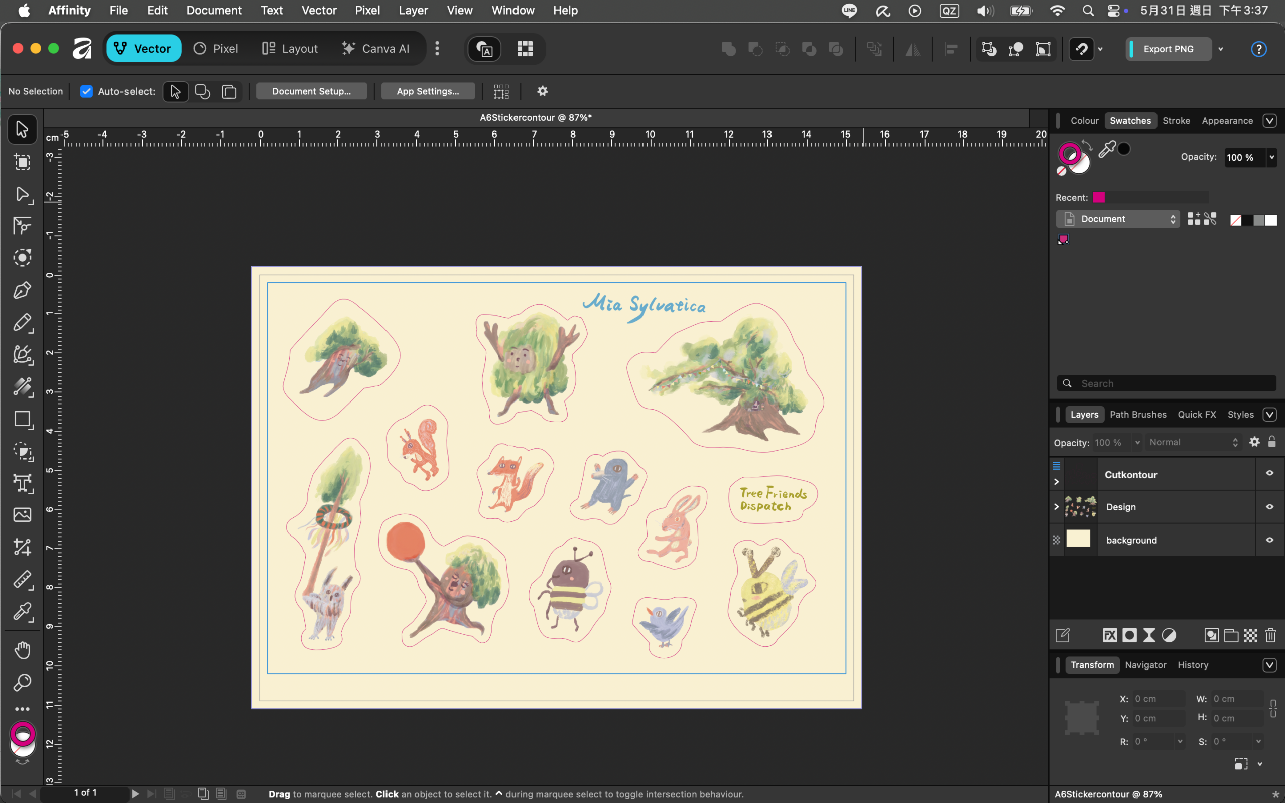
Creating Sticker Print Files: How I design stickers with Procreate + Affinity by Canva and create 2 mm cutlines
Below, I’m sharing how I created the latest Snail Mail Club stickers. I’ll take you through my workflow from Procreate to Affinity by Canva, preparing print-ready files that meet the printing vendor’s specifications.
But first, a critical warning! Before starting, please understand the potential risks that could lead to wasted effort, so you can consider whetherAffinity by Canva is the right choice for this project.
The printer I use requires PDF/X-4 files. Unfortunately, exporting PDF/X-4 from Affinity by Canva sometimes produces glitched or messy results, like the one shown below.
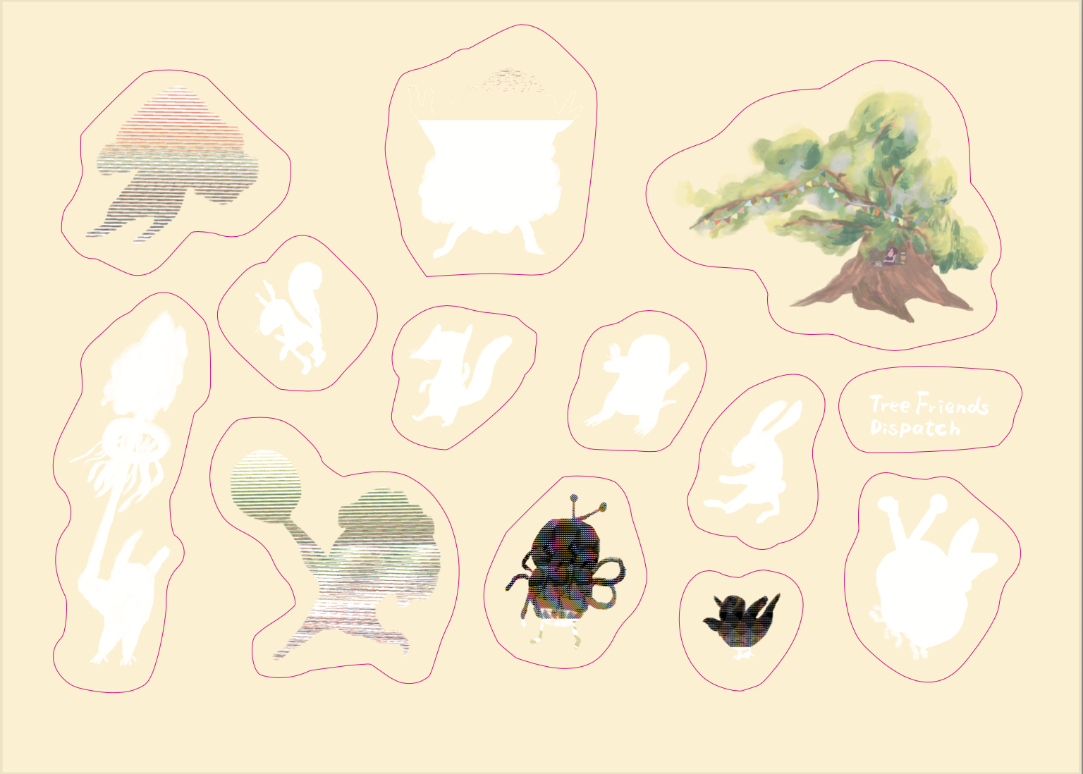
Based on what I found online, it seems like this is some kind of bug in Affinity by Canva. It only happens when exporting as PDF/X-4—other PDF versions or PNG files work completely fine. After experimenting back and forth so many times, my takeaway is that keeping your layers as simple as possible makes a successful export much easier. By that, I mean avoid having groups within groups, using complex blend modes, keeping hidden layers, or importing PSD files (especially if that PSD contains multiple layers or hidden ones).
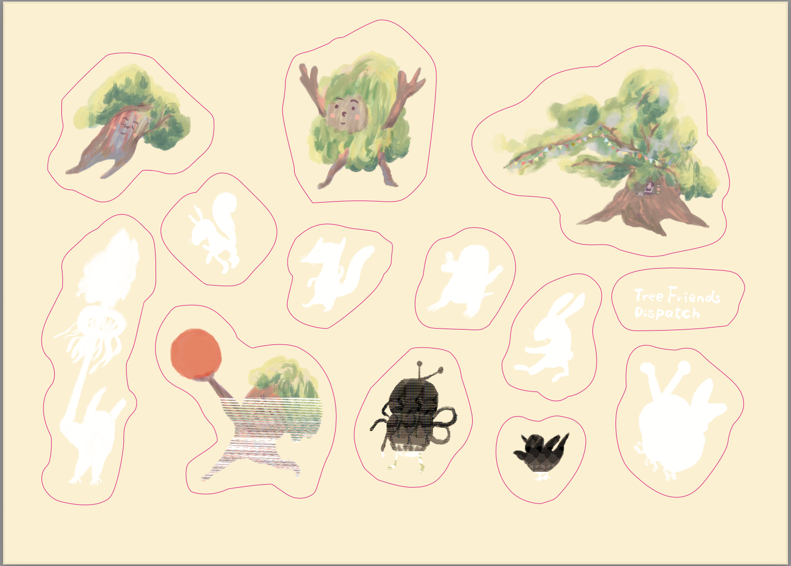
Sometimes I also swap the layer order and put the critical layers right at the top—and honestly, sometimes you just get lucky and it works by accident.In short, the PDF/X-4 export in Affinity by Canva is somewhat unstable, so please consider your options carefully. But if you don’t need this specific format, you shouldn’t have to worry at all. Overall, I find the software highly user-friendly and great to work with.
Reading the Printer’s Sticker Specifications
German printing websites usually provide product specifications or design templates, and I highly recommend downloading and reading them all. For this sticker project, the manufacturer provided the following spec sheet: https://www.flyeralarm.com/sheets/de/etikett_a6_bogen_cut.pdf.
Make sure to read through these carefully first, so you don’t end up exporting files with the wrong specifications.
The documentation emphasizes from the start that professional desktop publishing software supporting “spot color” configuration is required—such as InDesign, Illustrator, QuarkXPress, or CorelDraw; Affinity is also capable of doing this. General office documentation software (like Word) and pixel-based image processing software (like Photoshop without vector conversion) are inadequate for producing print-ready files for this product. The cutline, set as a spot color, serves as the path that instructs the cutting machine to slice the sticker or final product along that specific line.
Using FLYERALARM’s A6 sticker (custom/free-form shape) print specification document as an example, here are the key highlights:
Specifications & Production Guidelines
Document Bleed & Format
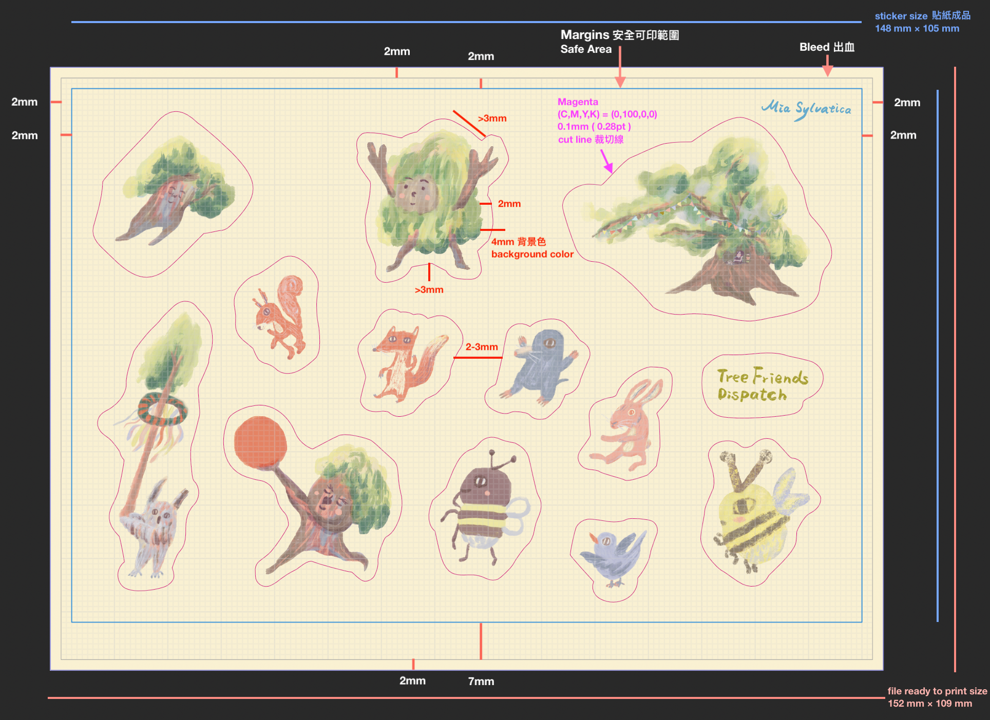
- Digital File Dimensions (Total canvas size including bleed): 15.2 cm×10.9 cm
- Printable Artwork Area (Actual layout area for stickers): 14.8 cm×10.5 cm
- Margins & Safety Limits: The distance (x) between the usable artwork area and the outer edge must be 2 mm.
- Safety Distance (y): Leave a 2 mm gap at the top, left, and right; a 7 mm gap is required at the bottom.
- Note: Alignment control marks (C) (dimensions: 10 mm×9 mm) will be automatically applied by the printer’s system at designated spots. Please leave this area completely clear in your design!
Cutlines
- Your artwork design (background color) must extend at least 2 mm outward past the cutline to avoid unwanted white borders (flashing).
- When planning your layout, avoid using excessive or overly complex vector graphics.
How to Create Cutlines
- Create the cutline on a separate layer and set it as a spot color of 100% Magenta.
- The spot color MUST be named exactly:
Cutkontour(case-sensitive). - The print file must only contain closed cut paths.
- The cutline must be set to “Overprint” enabled.
Additional Configuration Rules
- Set the cutline stroke weight to 0.1 mm (0.28 pt).
- It is imperative to use closed paths only.
- The only accepted file format is PDF/X-4.
- When setting up the cutline, the stroke alignment must be set to “Center”!
- Minimize the number of anchor points (control points) on the cutline as much as possible.
- The minimum distance between two separate cutlines must be at least 2 mm.
- Cutlines cannot be full-bleed (they must not extend into the outer bleed area of the A6 sheet).
- Cutlines should not have sharp corners; please apply a 3 mm corner radius.
- For all wavy lines, arcs, or jagged (pointed) elements, the height variance must not be less than 3 mm.
Important Notes:
- Custom-shape die-cutting is not suitable for highly intricate designs or extremely small text.
- The paths of two adjacent cutlines should never come closer than 3 mm to each other.
Layout Orientation Requirements
- Ensure that the orientation of your submitted file matches the reference diagram exactly.
- Rotating pages after exporting the print-ready PDF can result in incorrect print orientation on the final product.
- Any necessary orientation rotations for the print data must be done directly within your layout/design software.
Based on this document, I’ll walk you through how to set up and create your stickers step-by-step as I make them.
Procreate Drawing & Export File Specifications
First, determine the final size of your finished illustration. My personal rule of thumb is to draw on a canvas that is twice the size of the final product. For example:
- For an A6 final product → draw on at least an A5 canvas or larger.
- For an A5 final product → draw on at least an A4 canvas or larger.
- For an A4 final product → draw on at least an A3 canvas or larger.
Since the final printed product for this sticker batch will be A6 size, the file specifications are configured in the table below:
| Canvas Size | A5 Size + Bleed and Safe Printable Area (218 mm×161 mm) |
| Resolution | 300 DPI |
| Color Profile | RGB / Display P3 |
It is highly recommended to include the bleed and safe printable area in your Procreate canvas dimensions. You should also draw the guide lines for these zones yourself, ensuring you don’t place critical elements in the “danger zone” where they might get cut off or become unprintable. If your artwork goes all the way to the edge, make sure to extend it fully to—or even slightly past—the bleed line just to be safe.
Once that’s set up, have fun drawing your individual sticker elements!
After finishing your illustration, duplicate this Procreate file first. Open the duplicated file and follow these steps:
- Merge all layers into a single layer. Keeping it to just one clean layer helps prevent export glitches later when formatting in Affinity for print.
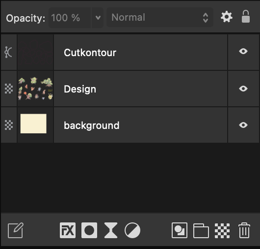
- Turn off the background layer.
- Export the file as a PSD.
(Optional) If your design has a background color, you can export the background layer separately as a PNG first, then delete it from your working file. The goal is to keep your sticker PSD file strictly limited to one single layer.
Affinity File Configuration & Setup
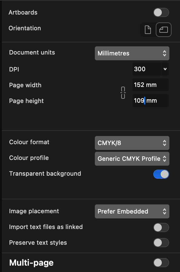
Open Affinity and create a new document. When the file settings panel appears, configure the settings according to the printer’s specifications and click “Create Document.”
The detailed parameters based on the printing vendor’s specifications are listed in the table below:
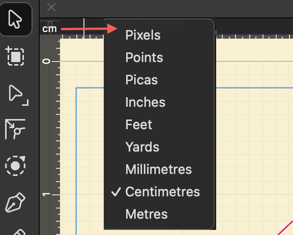
| Document units | Millimetres |
| DPI | 300 |
| Page width | 152mm (As stated in the specification document, A6 size including bleed.) |
| Page height | 109mm (As stated in the specification document, A6 size including bleed.) |
| Colour format | CMYK/8 |
| Colour profile | Generic CMYK Profile |
| Transparent background | ON |
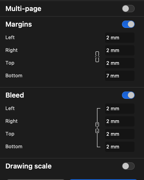
| Margins | Safe printable area: 2 mm for left, right, and top; 7 mm for bottom. |
| Bleed | 2 mm for left, right, top, and bottom. |
If you want to modify these parameters later, you can do so by going to the top menu and navigating to Document > Setup > Document Setup.
Once the document is created, name your file and save it first.
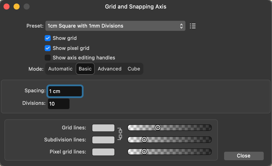
Once the document is created, you can turn on the grid by going to: View > Grid and Axis… (refer to the image below for settings). This sets each grid square to 1 mm.
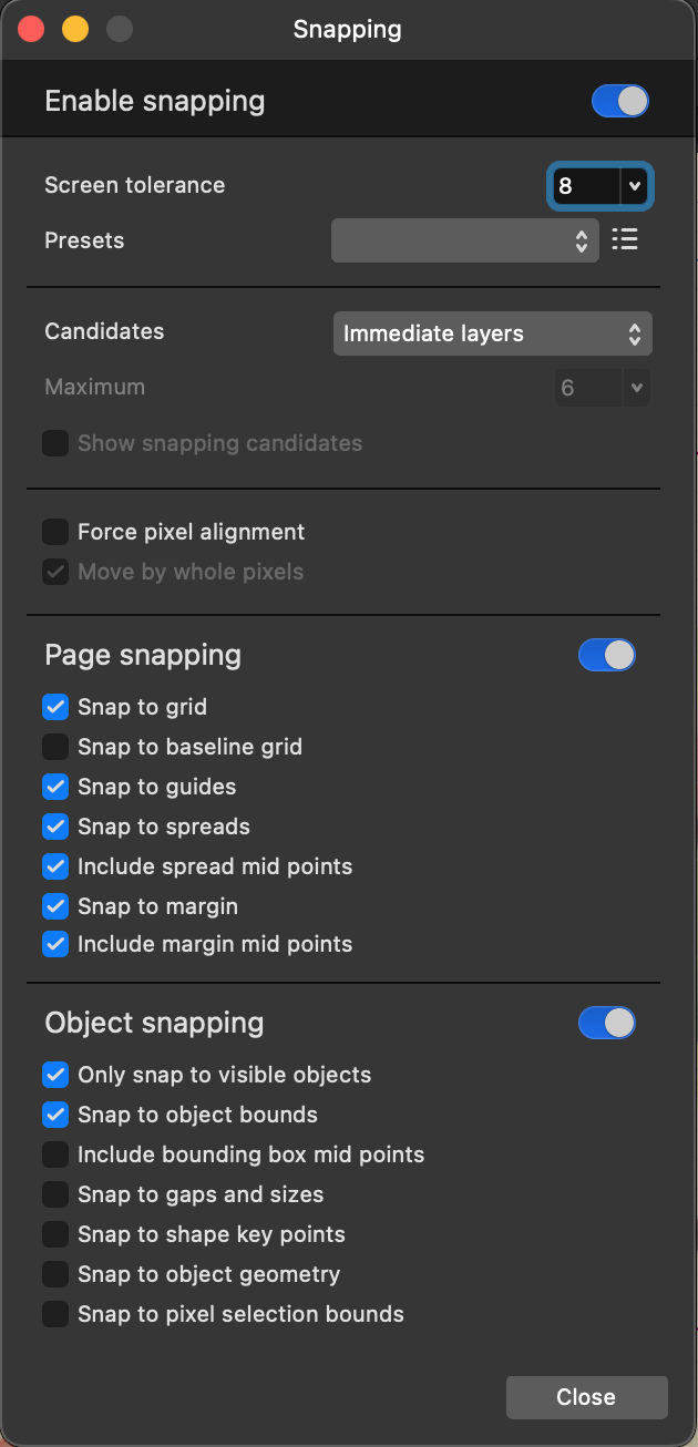
Turn on Snapping (View > Snapping…), which is extremely helpful for aligning elements. The snapping configuration is shown in the image below.
Separating Layers in Affinity
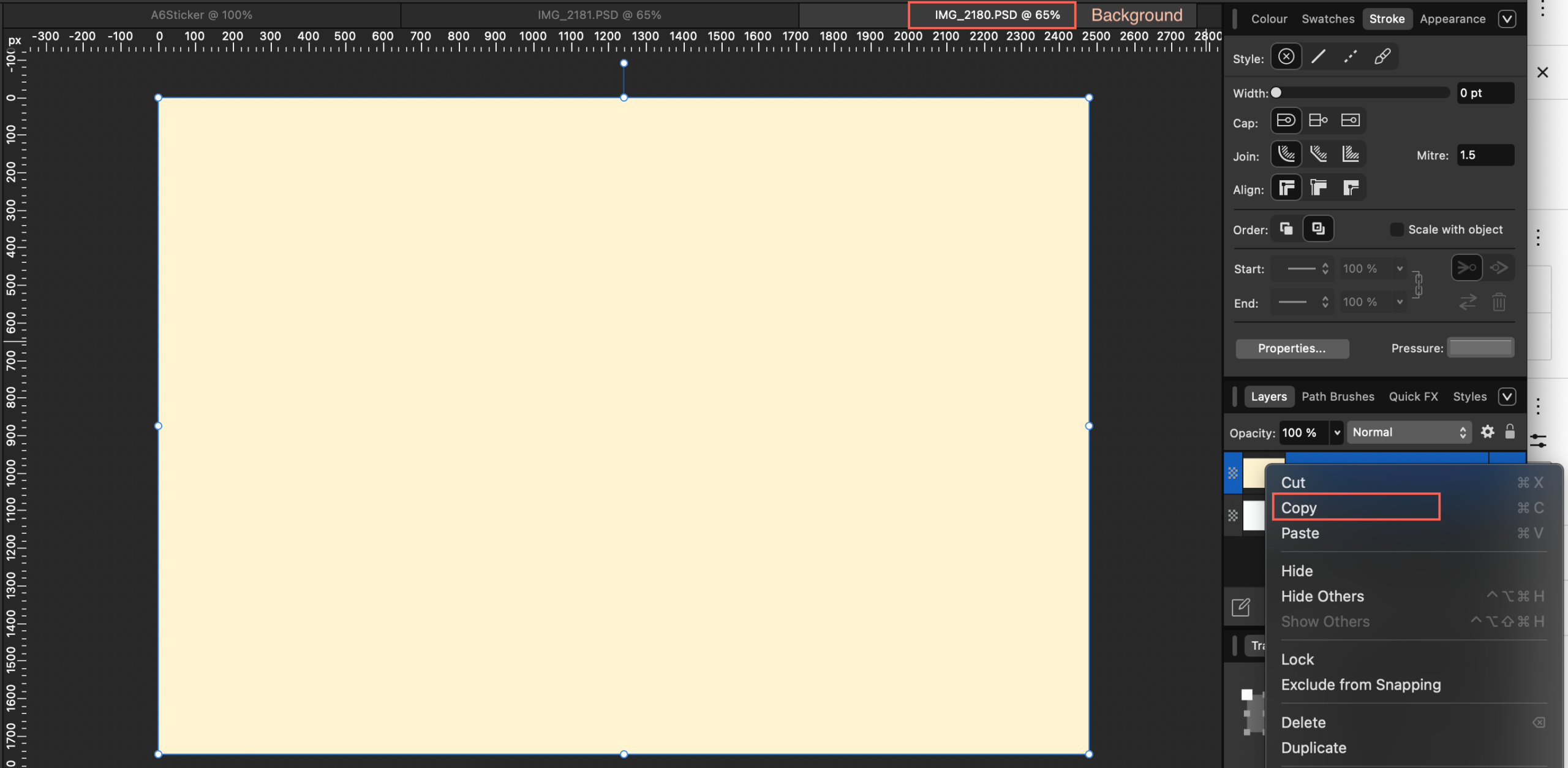
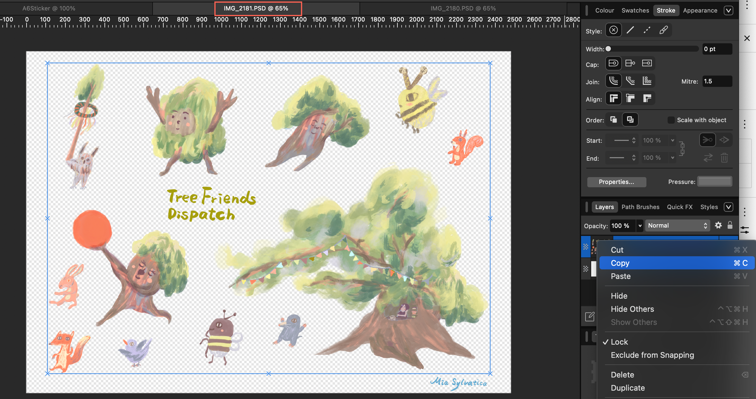
Open the sticker PSD file exported from Procreate in Affinity, then copy the PSD layer into the newly created A6 sticker print document. To minimize the risk of export errors, it is highly recommended to rasterize the layer right after pasting it: right-click and select “Rasterize…” (Alternatively, you can do this right before the final export).
ince my sticker elements need to be rearranged to meet the spacing regulations (and the rulers in layout software are much clearer than in Procreate), I need to separate the elements onto different layers. If you already finalized your layout back in Procreate, feel free to skip ahead to the “Creating Cut Paths in Affinity” section. The advantage of splitting them into separate layers is that it makes resizing and adjusting positions much easier later on.
The separation steps are as follows:
Step 1: Create a Red Contrast Layer
- In the Layers panel, make sure you do not have any layers selected.
- Click the Add Pixel Layer button (the icon looks like a checkerboard) at the bottom of the Layers panel.
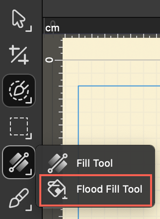
- Switch to the Flood Fill Tool (Paint Bucket Tool, shortcut G) on the left toolbar.
- Set the fill color to pure red in the Color panel, then click anywhere on the canvas to fill the entire new layer with red.
Q: Does the contrast layer for separating elements have to be red? Can I use magenta or blue instead?
A: It definitely doesn’t have to be red. You can change it to Magenta, Cyan (blue), or even green or yellow—any of them will work perfectly. For example, if your artwork contains a lot of green, using a pure Red background will provide the highest, most jarring contrast. This stark difference makes it much easier for the software’s selection brush to recognize the edges.
The Golden Rule for Choosing a Color: “Go Against Your Artwork’s Palette” The core strategy of this advanced technique is to create maximum contrast. Therefore, your choice of color should depend entirely on the dominant colors of your sticker design:
- If your artwork is mostly blue or green: Using Red or Magenta will give you the best results.
- If your artwork is mostly red, pink, or orange: Using red will fail because the colors will blend together. In this case, switching to Cyan (blue) or Green will create a sharp contrast, making your selections incredibly precise.
Step 2: Change the Blend Mode and Group the Layers
- Select the pixel layer you just filled with red. In the Blend Mode dropdown menu at the top of the Layers panel, choose Color Burn or Color Dodge. You will notice the colors of your artwork suddenly shift to an extreme, high-contrast look. (Feel free to experiment with different blend modes to see which one gives you the sharpest contrast. For certain light-colored designs, switching to Color Dodge or Multiply can yield surprisingly good results.)
- Right-click your original sticker layer and select Duplicate (or press Ctrl+J / Cmd+J).
- Select both the “Red Layer” and the “Duplicated Sticker Layer” at the same time, right-click, and select Group.
- Right-click this newly created group and select Rasterize…. This bakes the high-contrast effect permanently into a single, independent layer.
Step 3: Make Precise Selections
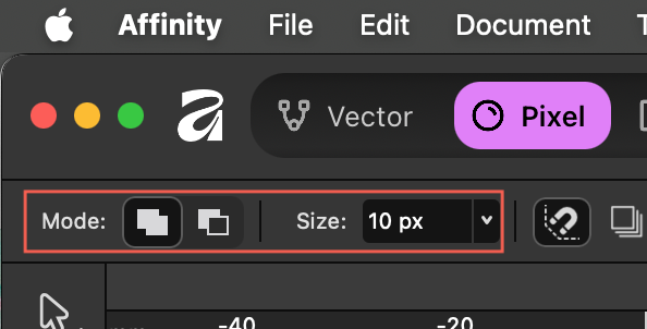
- Switch to the Pixel.
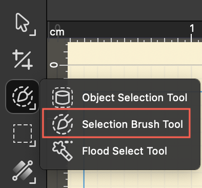
- Click the Selection Brush Tool (shortcut W) on the left toolbar, and make sure the mode at the top is set to Add.
- Thanks to the boosted contrast, you can now simply paint over the element you want to separate, and the selection marquee will perfectly and rapidly snap to the edges. If the brush selects too much, switch the mode to Subtract to clean up the overextended areas.
Step 4: Copy and Paste the Element from the Original Image
- While the selection marquee (marching ants) is still active, click and select your original sticker layer.
- Press Ctrl+C to copy, and then Ctrl+V to paste (Cmd+C / Cmd+V on a Mac).
- Check your Layers panel—you will see that the selected design has been perfectly separated onto its own brand-new layer!
Step 5: Clean Up and Repeat
- Before selecting the next element, make sure to clear your current selection by going to the top menu and clicking Select > Deselect, or by using the shortcut Ctrl+D / Cmd+D.
- To cut out the next design, simply turn the visibility checkbox for your high-contrast red layer back on, and repeat Steps 3 and 4.
Creating Cut Paths in Affinity
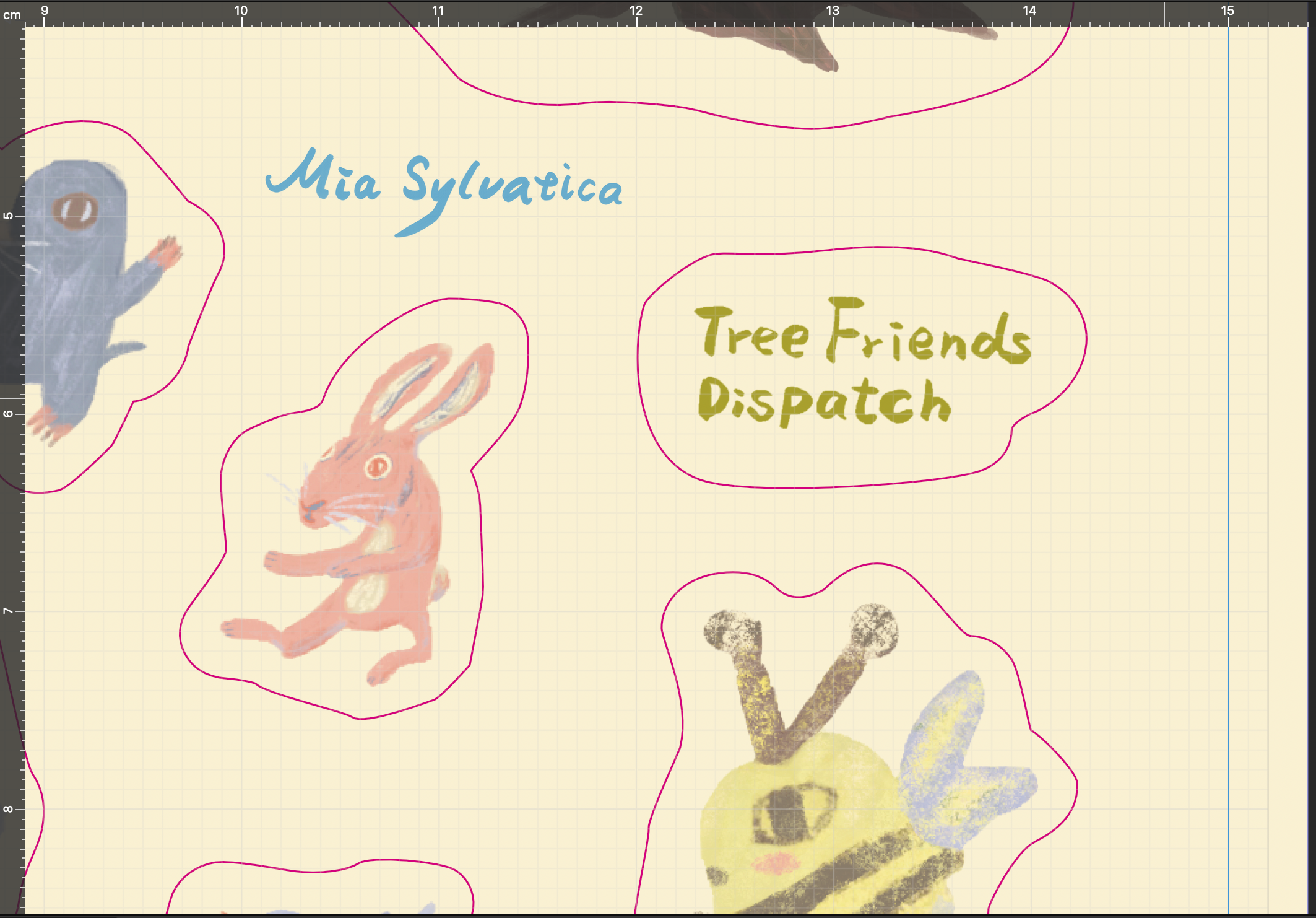
Select the layer you want to create a cut path for. Next, we will begin drawing the cut paths.
According to the specification document, we need to create a 2 mm bleed, a 2 mm safety distance, and a 0.1 mm cut line width (Magenta). The safety distance means each sticker element must be at least 2 mm apart from one another—do not place them too close together. The steps to create the cut path are as follows:
Step 1: Select the Sticker Elements
- Use the Move Tool (Black Arrow, shortcut V) to marquee-select all elements of your designed sticker artwork.
- Press Ctrl+J (Cmd+J on Mac) to duplicate them.
- Right-click and select Group.
- Follow Steps 1 through 3 from the previous section (Separating Layers in Affinity) to select each element. (You can select all elements at once, or select each element separately to create individual cut lines. Click here to read how to properly merge cut lines into a single, independent layer.)
Step 2: Create the 0.1 mm Magenta Cut Line and 2 mm Bleed
When a printing machine cuts paper, tiny physical shifts inevitably occur. If the background color of your sticker elements perfectly aligns with the cut line, even a slight misalignment during cutting will expose a white edge. To prevent these white gaps, the background color must extend past the intended cutting edge by at least 2 mm. This ensures that even if the blade shifts slightly, it will still cut within the colored background.
- Switch to the Vector.
- Click the Contour Tool (shortcut O) on the left toolbar.
- Configure the stroke style to meet the print specifications: In the Color panel on the right, set Fill to None.
- Set the Stroke color to 100% Magenta (Process Magenta).
- Open the Stroke panel to configure the following details:
- Width: Type in
0.1 mm(or0.28 pt). - Align: You must select Align to Center.
- Join: Select Round Join (this prevents sharp corners from piercing or tearing the paper).
- Width: Type in
- In the Radius field on the top context toolbar, type in
2 mmand press Enter. (The line will expand outward by 2 mm all the way around). - Click Bake Appearance on the top context toolbar. (Crucial step!! Otherwise, the path nodes will remain on the inner ring rather than on the outer contour line).
- In the Layers panel, name this specific layer “Cutkontour” (or whatever exact name your printing vendor requires).
Tip: Since this is your first time making stickers, keep it as simple as possible! Design the entire sticker background and the area within the bleed line using a single solid color. That way, all you need to do is draw a single outline that sits 2 mm away from your artwork!
If the colors inside and outside the contour line are different, you can follow these steps
Step 1: Create the 0.1 mm Magenta Cut Line
- Switch to the Designer Persona (Vector mode).
- Click the Contour Tool (shortcut O) on the left toolbar.
- If you want the cut line to perfectly hug the original edge of your artwork, click Bake Appearance on the top context toolbar right away.
- Configure the stroke style to meet the print specifications: In the Color panel on the right, set Fill to None.
- Set the Stroke color to 100% Magenta (Process Magenta).
- Open the Stroke panel to configure the following details:
- Width: Type in
0.1 mm(or0.28 pt). - Align: You must select Align to Center (the middle icon).
- Join: Select Round Join (this prevents sharp corners from piercing or tearing the paper).
- Width: Type in
- In the Layers panel, name this layer “Cutkontour” (or the exact name required by your vendor) and place it at the very top.
Step 2: Create the 2 mm Outward Background Bleed
- Select the Cut Line object you just created, and press Ctrl+J / Cmd+J to duplicate it.
- Drag this newly duplicated object to the very bottom of the Layers panel (to serve as your background base).
- Switch back to the Contour Tool (shortcut O).
- In the Radius field on the top context toolbar, type in
2 mmand press Enter. (The line will expand outward by 2 mm all the way around). - Click Bake Appearance on the top context toolbar.
- Use the Color Picker Tool (Eyedropper Tool, shortcut I) to sample the background color from the outermost edge of your sticker, and fill this larger shape with that color. Now, your background perfectly extends 2 mm past the cut line.
Step 3: Check for Closed Paths
A “Closed Path” means that the start and end of a line must connect perfectly to form a complete, continuous shape (like a perfect circle, square, or any seamless loop). If a path has a gap (an open path), the cutting blade of the plotting machine will stop halfway, or the sticker won’t peel off properly from its backing paper.
Examine your cut lines carefully. If you drew them using the Pen Tool, make sure the start and end points are fused together; there must be absolutely no broken segments.
Method 1: The “One Object, One Layer” Check
This is the easiest approach—you can tell instantly just by looking at the layer label:
- Open the Layers panel on the right.
- Locate your cut line object and look at the label in parentheses next to its name:
- Curves (plural with an “s”): This means it is an open path (there is a break somewhere; it fails inspection).
- Curve (singular without an “s”): This means it is a closed path (the start and end are connected; it passes inspection).
📝 Note: If the path was created using shape tools, it will display as Rectangle, Ellipse, etc., which are closed paths by default.
Method 2: Check the Ends with the Node Tool
- Select the Node Tool (White Arrow, shortcut A) on the left toolbar.
- Click on your cut line to display all of its vector anchor points.
- Look at the start and end points: If it is an open path, you will see that one of the nodes is noticeably larger, or you will see two distinct endpoints. If it is a closed path, all nodes will be identical in size, with no visible “head” or “tail.”
Method 3: The Fill Test (Visual Inspection)
- Select your cut line.
- Apply a solid color fill to it via the color panel.
- Observe the shape closely: If one side lacks a border (Stroke) but the fill color is harshly cut off along a straight line between two points, it is an open path. If the fill color is perfectly contained inside a continuous border, it is a closed path.
What if I find an “Open Path”? How do I close it?
If your check reveals that it is a broken path (Curves), do not worry—there is no need to manually redraw it. Affinity has a built-in feature to fix this instantly:
- Switch to the Node Tool (shortcut A).
- Click on the broken path to select it.
- On the top action toolbar, click the Close Curve button.
Step 4: Organize Your Layers
The printing vendor requires the cut lines to be on an independent layer, and the final file format must be exported as PDF/X-4.
- The First Layer (Named “Cutkontour” per the vendor’s specifications): Place only the 0.1 mm Magenta cut line inside this layer. The cut lines must reside on their own separate layer; however, the vendor’s specification document does not state that it must be at the very top. (Note: Keep this as a vector path; do not rasterize it.)
- The Second Layer (Named “Design”): This is the layer for your artwork elements. (You can group your multiple design layers together, rasterize the group, and name it “Design”).
For your final layers, either of the following two setups will export successfully:
Q: If my cut lines are on different layers and I merge them into one, they turn into pixels and are no longer vectors. Will this cause an issue for the commercial printer?
A: Yes, it will be a major problem. If your cut lines turn into Pixels (rasterized/bitmap images), they become nothing more than a grid of colored squares to software. A print shop’s digital cutting plotter relies entirely on vector nodes and line paths to guide its blade. Without vector paths, the machine will have no idea where to make the cuts.
The correct way to consolidate multiple cut lines into a single Cutkontour layer in Affinity is as follows:
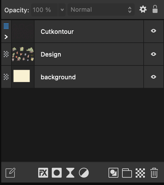
- Create a dedicated “Container Layer”: Click the Add Layer icon (the icon looks like a folder or a stack of sheets) at the bottom of the Layers panel, and name this new layer
Cutkontour(or the exact name required by your vendor). - Drag and drop the lines inside: Use the Move Tool (Black Arrow, shortcut V) to select all of your vector cut lines. Then, in the Layers panel, drag and drop these objects directly into the
Cutkontourlayer so they become its child elements. - Do NOT select “Rasterize” or “Merge Down”.
Cut Line Final Checklist
When you select a cut line and switch to the Node Tool (White Arrow, shortcut A):
- Incorrect (Pixel/Raster): Clicking it does absolutely nothing, or you only see a standard bounding box around the image.
- Let me know if you need any adjustments or further clarifications!
Setting Up a Cut Line Spot Color in Affinity
To create a spot color named “Cutkontour,” follow these steps in Affinity:
- Open the Swatches panel on the right.
- Click the panel options menu button (the small menu icon) in the top-right corner of the panel, and select Add Global Color. Note: In Affinity, a color must be a Global Color before it can be converted into a spot color.
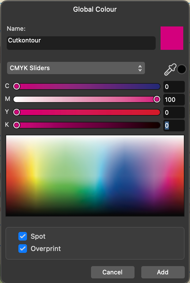
- In the pop-up settings window, configure the following:
- Name: Type
Cutkontour(make sure to follow the exact capitalization and do not include spaces). - Color Mode: Select CMYK.
- Values: Set to C=0, M=100, Y=0, K=0 (100% Magenta).
- Name: Type
- The Most Critical Step: Check both the Spot color and Overprint boxes at the bottom of the window.
- Click Add.
You will now see a magenta swatch appear in your Swatches panel with a small triangle indicator in the corner, confirming that it is successfully set as a spot color.

Verifying Cut Lines and Bleed
Verify Cut Line Color and Thickness
- Select the cut layer you created earlier.
- Apply the Color: Select your cut line, and set its Fill to None (Transparent). Set its Stroke to the
CutkontourSpot Color you just created. - Set the Stroke Width to 0.1 mm (0.28 pt), per your print vendor’s specifications.
Check the Bleed
- Ensure that both your sticker artwork and the
Cutkontour(cut line) remain within the safe margin area (with a 3 mm gap) that you set previously. - Go to the top left menu and click File > Document Setup….
- Switch to the Bleed tab, and set the Top, Left, and Right margins to 2 mm, and the Bottom margin to 7 mm.
Set the Cut Line to “Overprint ON”
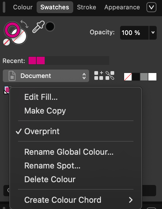
If you forgot to check this option when setting up your spot color, follow these steps to turn it on:
- Use the Move Tool (Black Arrow, shortcut V) to select your cut line object (the 0.1 mm Magenta line).
- Open the Swatches panel on the right.
- Right-click the Magenta swatch icon located under the Document palette, and select Overprint.
About Overprint
1. What is “Overprint”?
In design and printing software, when two colored objects overlap, the computer’s default processing method is called “Knockout.”
- Default (Knockout): When printing the bottom background layer, the press will leave a blank “white hole” where the top line (the cut line) sits, and then print the line precisely over that white gap.
- Overprint ON: The press completely ignores the top line and prints the entire background layer solid and uninterrupted. Afterward, it prints the cut line directly on top of the already printed background.
2. Why Must Cut Lines Have “Overprint” Turned On?
This 0.1 mm Magenta line is strictly meant to guide the digital cutting plotter; it is not meant to appear on your final printed product. Before hitting the print queue, the vendor will use prepress software to hide or turn off this line so it doesn’t print.
- If Overprint is OFF (Default Knockout): Even though the vendor hides the cut line, a 0.1 mm wide white, unprinted outline will still be left behind on your sticker background.
- If Overprint is ON: When the vendor hides the cut line, the underlying background remains perfectly solid, seamless, and intact.
Therefore, enabling overprint is crucial to ensure that the cut line… (Note: The original text cuts off here, but the sentence would naturally conclude as: “…does not leave unwanted white gaps in your artwork after it is removed for printing.”)
Exporting to PDF/X-4 for Print in Affinity
- Click File > Export…
- Select the PDF format, and choose the PDF/X-4 preset.
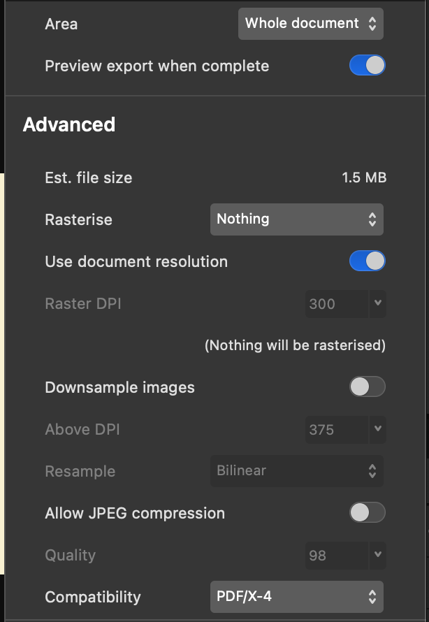
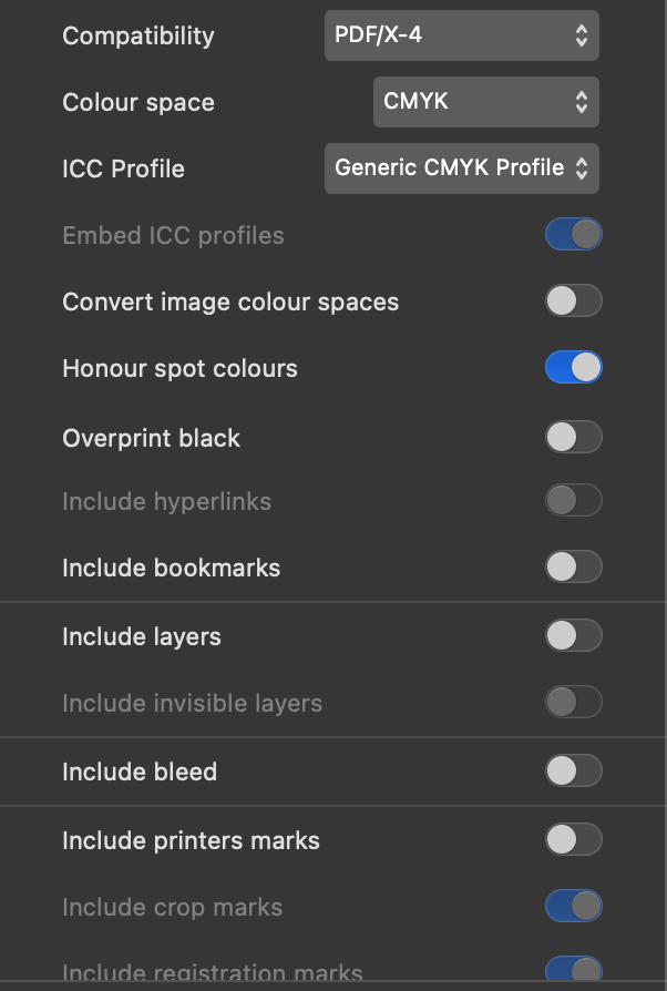
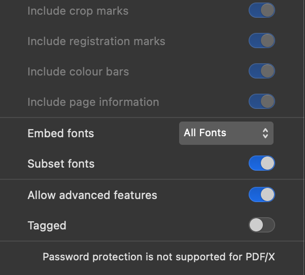
- Configure the key parameters as shown in the table below:
| Item | Value | Explanation |
| Area | Whole document | |
| Rasterise | Nothing | |
| Use document resolution | ON | |
| Downsample images | OFF | Options for screen output, such as JPG and PNG |
| Allow JPEG compression | OFF | Options for screen output, such as JPG and PNG |
| Compatibility | PDF/X-4 | |
| Colour space | CMYK | |
| ICC Profile | Generic CMYK Profile | |
| Honour spot colours | ON | Important! For Cut Line Spot Color |
| Overprint black | OFF | Turn this on to fix white gaps/halos on small text |
| Include layers | OFF | |
| Include bleed | OFF | The file dimensions required by the printer already include bleed |
Q: When should I UNCHECK “Include bleed”?
A: When exporting a PDF, if you leave “Include bleed” unchecked, the document’s bleed area will be automatically cropped out (it won’t be visible) in the final exported file.
If you have already factored the bleed directly into your canvas dimensions (for example, you are printing an A6 product, and you set your file’s width and height to the printer’s required size of 152 × 109 mm instead of the standard 148 × 105 mm), you do not need to check “Include bleed” during export. Doing so would add an extra layer of bleed, making your final file size too large.